Accessing and dumping firmware through UART
Introduction
In the first part of my hardware hacking series (located here https://www.arashparsa.com/introduction-to-firmware-hacking/) we discussed dumping firmware through the SPI flash chip. In this post, we will attempt accessing and dumping the firmware of a device through an alternative serial interface called UART.
We will first begin by discussing what UART is, why we would want to access a device through UART, and finally, how to go about identifying and accessing an arbitrary UART interface on any device.
What is UART?
Before we get into breaking a device and accessing it through its UART interface, let's first discuss what UART is and how it's used on a high level.
UART stands for Universal Asynchronous Receiver-Transmitter. It is used for asynchronous serial communications to send and receive data from devices for purposes such as updating firmware manually, debug tests, or just generally interfacing with the underlying system (kind of like opening a new terminal in Ubuntu). UART works by communicating through 2 wires (a transmitter wire and a receiver wire) in an attempt to talk to the microcontroller or system on a chip (basically the brains of our device) directly.
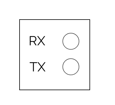
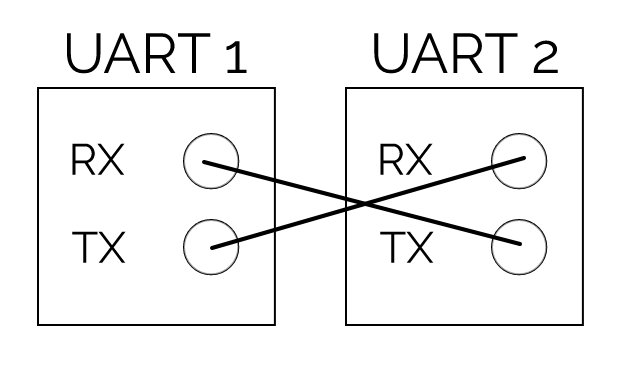
The receiver and transmitter, marked RX and TX respectively, need to connect to a second respective UART device's TX and RX in order to establish communications.
Once the UART communication begins, bits are read at a specific frequency called the "baud rate". This baud rate can differ between the devices by up to approximately 10% before the timing of bits gets too far off and data is corrupted.
With the proper cabling and baud rate, the 2 devices can now communicate successfully. By accessing a device's UART interface you will generally get presented a bash terminal of sorts to access the firmware. With this you can traverse the filesystem and execute arbitrary commands, view web files, find 0 days in binaries, you can find scheduled tasks, back-doors, and try to understand generally how the device works.
Why bother with UART?
So you may be wondering, we can already dump the firmware of a device through its flash chip, why would we need to access it or dump its firmware through UART instead?
If you recall in part one of the series, an issue users may occasionally encounter when trying to dump an SPI flash chip is powering on too much of the device through the VCC connection, thereby subsequently forcing the flash chip to be in use by the SoC (system on a chip) and preventing us from dumping the firmware. One solution could simply be to de-solder the flash chip and try again. This solution can be a bit of work though, requires additional tools (like a heat gun or de-soldering iron) that you may not already have, and even if you're successful you may find you just dumped an encrypted firmware that now you have to decrypt as well.
By using UART, we can talk to a device directly while the firmware is unencrypted in memory and running live, allowing us to dump it without having to de-solder a flash chip or non trivially decrypt an encrypted firmware. Not only that, but we can also view how the system changes in real time as we attempt to access it and find vulnerabilities.
What to look for
Within the world of embedded devices, UART interfaces are usually identified by searching for 4 holes/connections fairly close to the microcontroller/SoC of the board. Why four connections when UART is only two? Two of the connectors are for TX and RX for communications, one is for VCC to power the UART separately, and finally one is the ground to synchronize the connection between the devices.
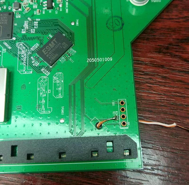
As we can see in figure 3, there are what looks like 4 holes on the edge of the board near the SoC and "guts" of the device. This is a UART interface for the TP-Link Archer C7 AC1750 router (thanks to https://openwrt.org/toh/tp-link/archer-c7-1750).
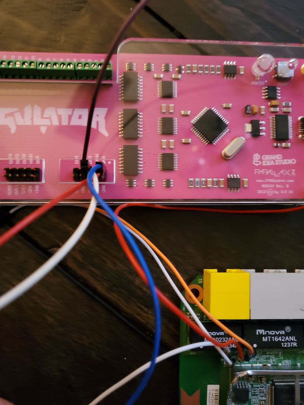
Unfortunately, as we can see here, we may have identified a potential UART interface, but the connections are not clearly labeled as to which is RX, TX, VCC or GND. Fortunately, we can use our fancy Jtagulator (http://www.grandideastudio.com/jtagulator/) along with a multi-meter to figure it out.
Accessing UART - The Process
For this post we will be attempting to access the UART interface to our Belkin N300 router from part one. First, before we can begin brute forcing anything with our Jtagulator, we will need to identify a common ground to use between the 2 devices. We can identify a ground using our multi-meter.
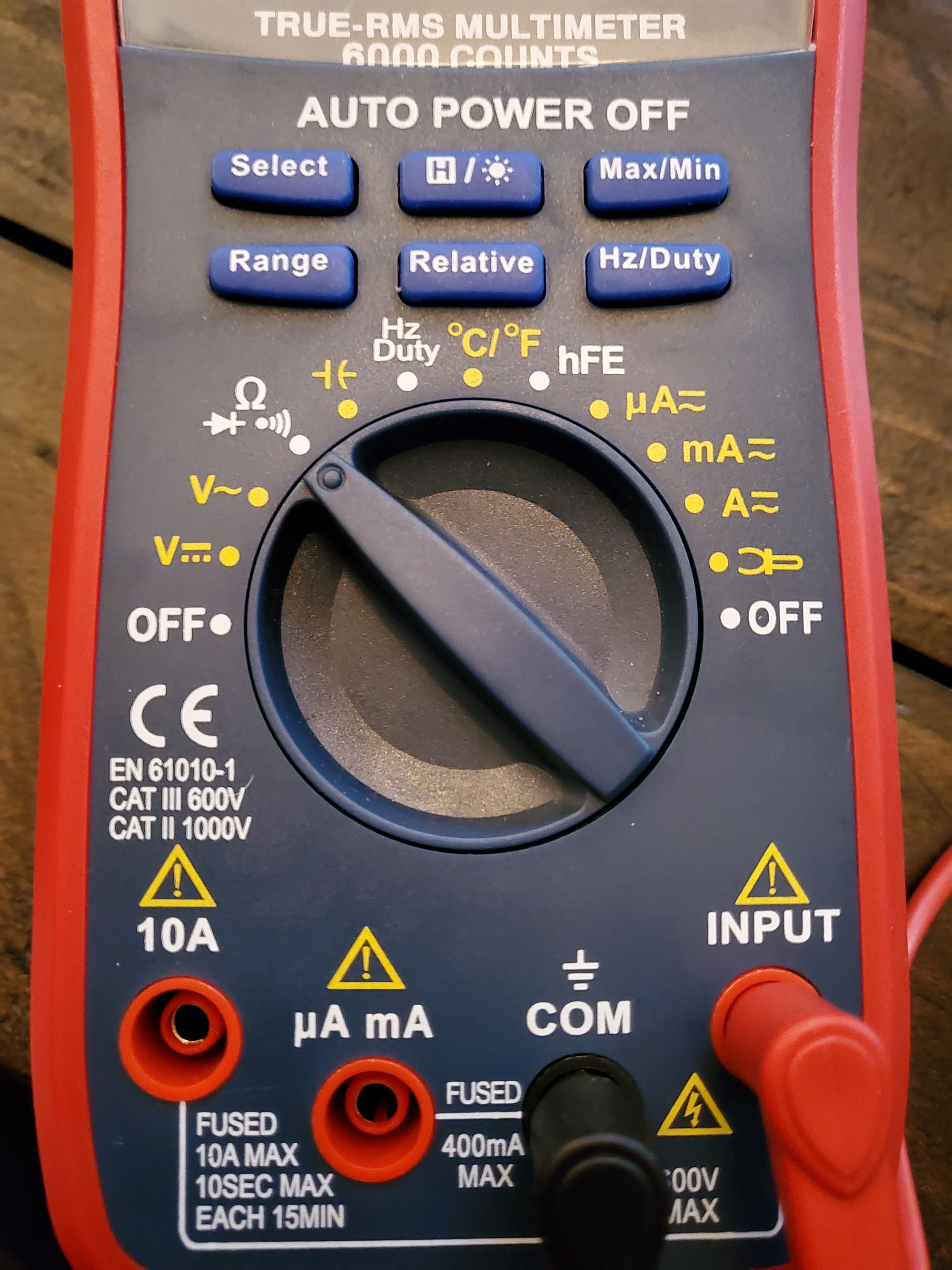
To find a ground, set your multi-meter in continuity mode (see figure 4). Once in continuity mode set the black probe to any shielding or metal on the device outside of the circuit and set the red probe on each connection until a value of 0 (or near 0) appears or a beep is heard indicating continuity. This pin with a value of 0/beeping is your common ground moving forward.
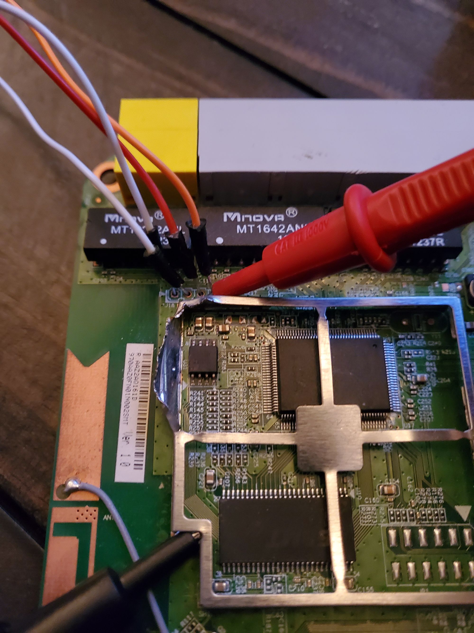
Figure 5 shows four soldered in male to male jumper wires to simplify this process of connecting to our second UART device for communications. It also shows the multi-meter probes connected inspecting each cable for a ground. A ground was discovered on the leftmost pin.

Now we can connect our cables and begin the brute force with our Jtagulator to identify the RX and TX cables. Connect the ground identified on the router to the ground on the Jtagulator and connect the final 3 pins to Channels 0-2 (make sure not to plug in to VADJ as this can send additional power to the device and may burn it!) as seen in figure 6 and we're ready to brute force.
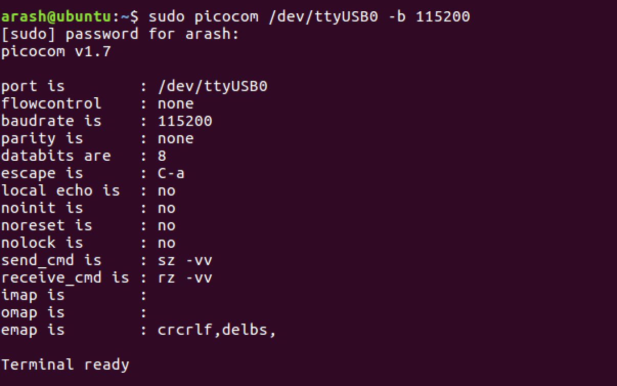
Now we need to access our Jtagulator using a serial console access tool. I'm a fan of using picocom. The Jtagulator communicates over a baud rate of 115200 so we will connect to its serial interface with a baud rate of 115200 using picocom and should get presented with a shell.
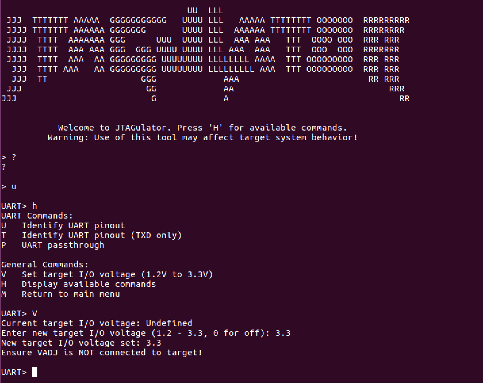
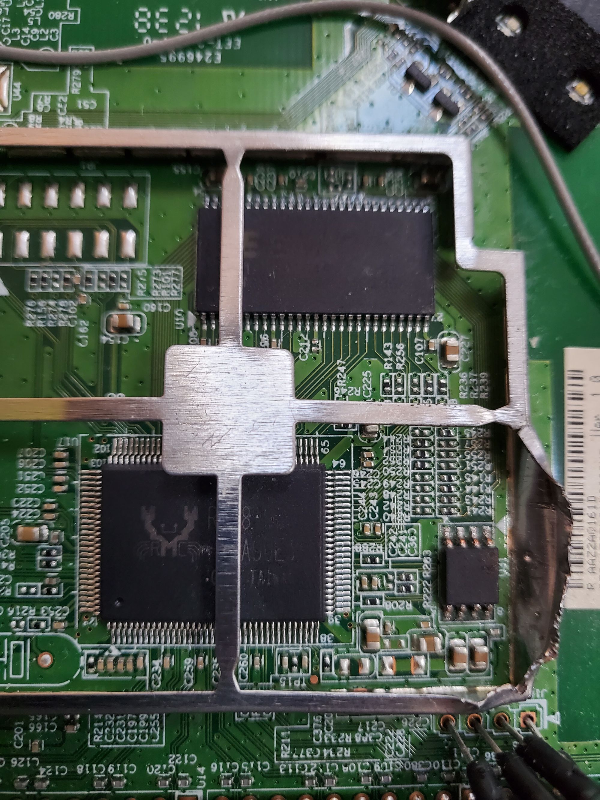
Upon connecting with picocom we are presented with a terminal for the Jtagulator. Going through the menu options we can identify the UART brute forcing tool and switch to it with the switch "u". Once in UART mode we must set a target voltage with "V" for the SoC. We can identify the UART voltage by identifying an SoC on the board and finding the relevant datasheet. For our Belkin N300, we identify an RTL8196C SoC chip and the relevent datasheet is found here: https://www.datasheetq.com/datasheet-download/706925/1/Realtek/RTL8196C. The proper voltage for our chip is 3.3.
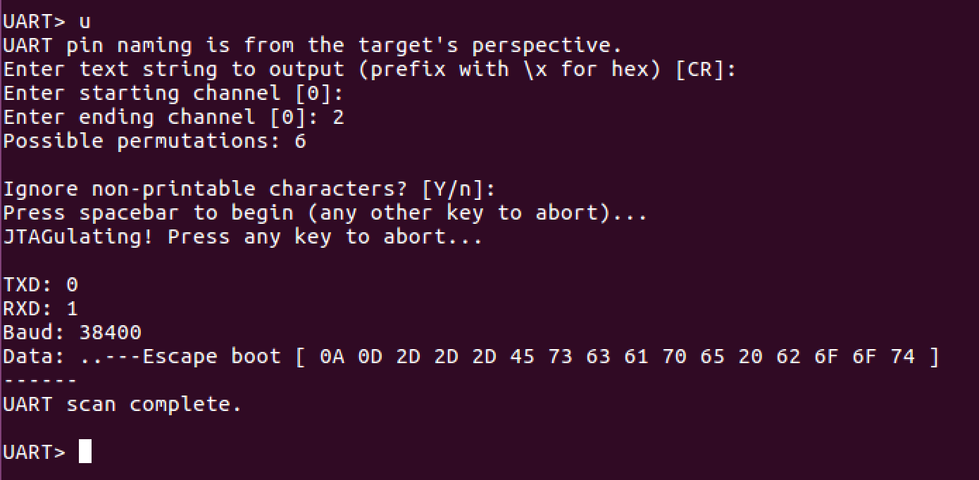
We begin a brute force finally by typing "u". Before explaining the options we entered I'll quickly explain how this brute force works.
The way the Jtagulator brute forces UART is by attempting to send and read data to and from every pin and every baud rate and shows data to the user so the user can determine which permutation is possibly correct. We can choose what to send through TX (in this case carriage return, or new line, as the default) and then we choose to display only ascii printable characters to ensure the output is proper human readable text. In this case we are hoping that sending a new line on all channels returns human readable output at some point. We also make sure to let the Jtagulator know that pins 0-2 are all the ones that are plugged in and ready to brute force. This won't always immediately return output, so it's advised you also plug in the device being tested immediately before starting the brute force so you can view output as it's booting as well (in case your TX fails for any reason you can still identify RX at least with this method). With this, we hit enter, begin brute forcing, and discover that when pin 0 is TXD, 1 is RXD, and the baud rate is 38400 we get what appears to be human readable output.
To confirm these parameters are valid we simply switch to UART passthrough with the "p" parameter, set TXD to 0, RXD to 1, and baud to 38400. I then type "help" and hit enter to verify we have a proper shell with input and output.
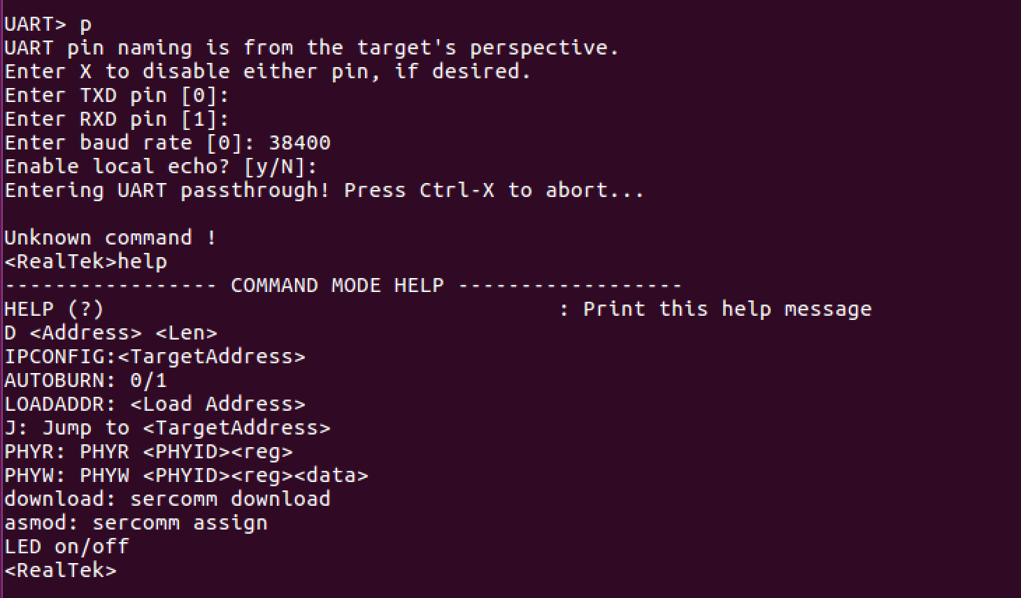
Success! We've successfully identified the UART pins on our device and established a serial console connection. Unfortunately, it appears as if our current console doesn't really provide us access to much, but the fix to this was easy.
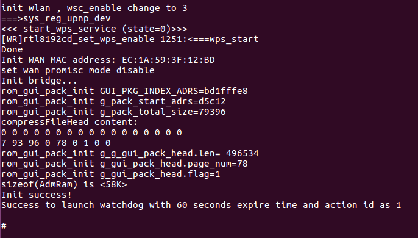
Restarting the device again to see boot output we can observe a boot all the way to a secondary root shell that makes it seem like our first shell is a recovery shell that appears when the boot process is interrupted by pressing any key.
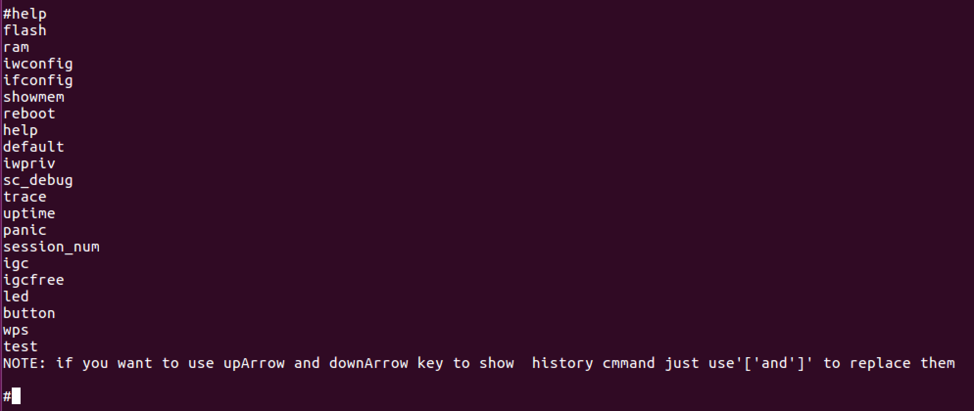
Within this shell unfortunately we were still restricted as it didn't appear to be any sort of full Linux shell. It was difficult to tell if this was a jail or sandbox of some sort or if this was naturally how the firmware presented a console. Playing with the different commands we identify the "flash" command as a potentially valid, alternative, mechanism to dump the firmware off the device.
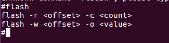
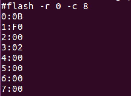
We can see "flash" basically accepts an offset parameter and a count parameter which leads me to speculate it can be used to dump a certain number of bytes of flash memory starting at any offset. Using this I attempt to dump all the bytes of the firmware but hit a snag....it appears dumping a large number of bytes with the flash command actually causes the device to crash and reboot!
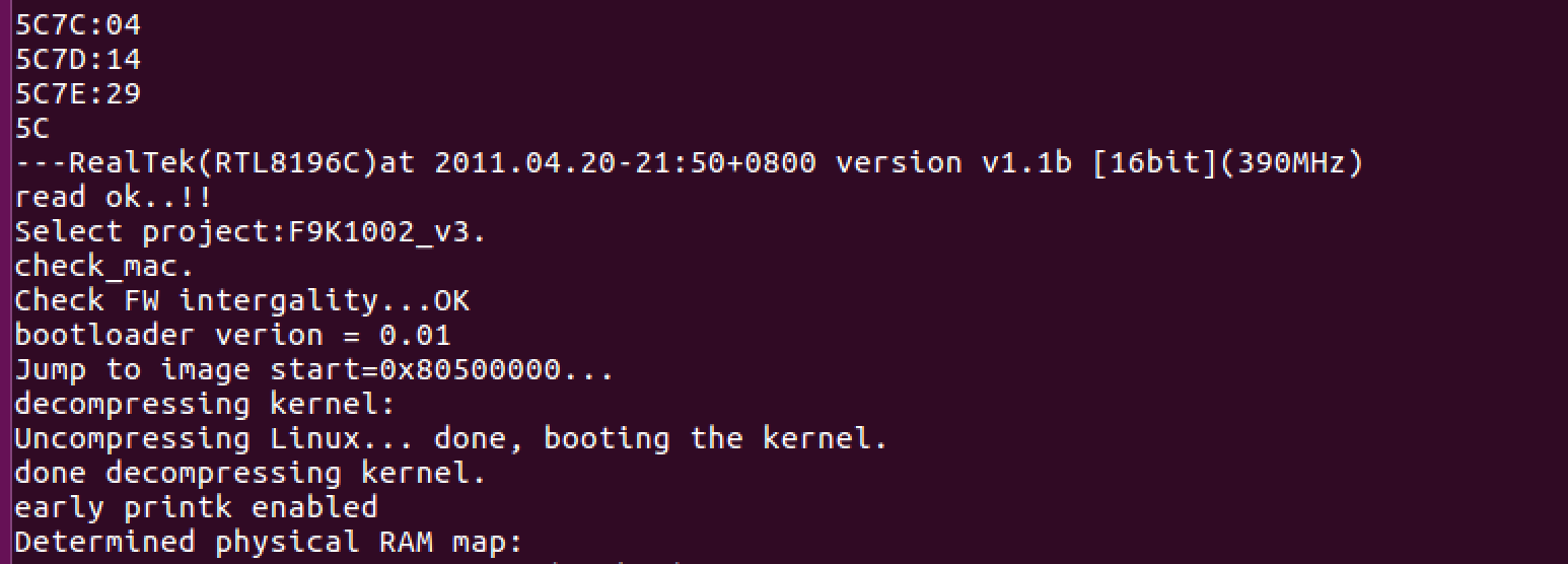
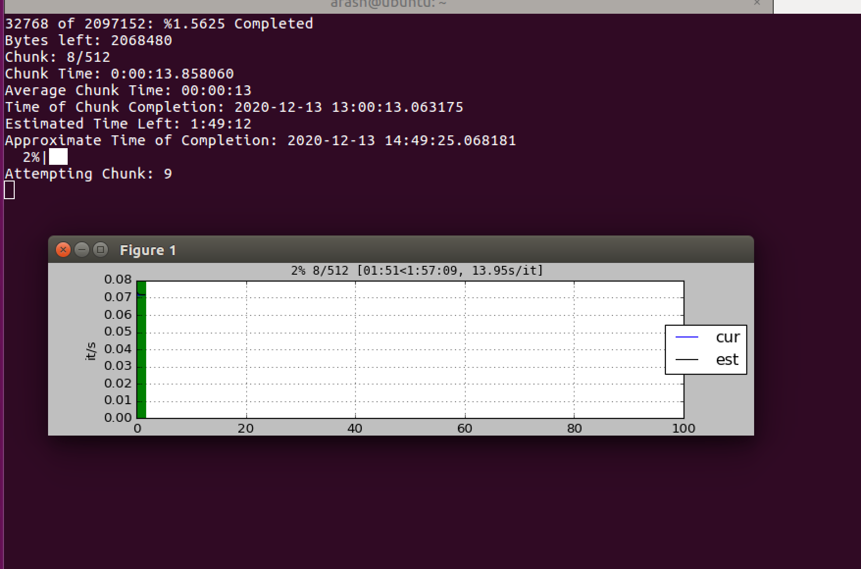
Whether this was some security mechanism or fault within the firmware itself was difficult to identify, but after some time working in Python land I was able to develop a script to establish a serial connection and dump 4096 bytes at a time to bypass this restriction and slowly dump all 2 million bytes with 512 requests. Because of the offset being output along with the bytes, I was also able to implement a simple integrity check to ensure all bytes existed and were of proper length and if incorrect, I am able to force a retry of the current chunk. The scripts used to dump this firmware can be found here: https://github.com/waldo-irc/IOTToolkit/tree/master/FlashDumpScript.
After about 2 hours the script completes and provides an output.bin file with all the bytes as plaintext. Using my DumpToBin.py script we can convert the text file to a valid firmware bin.
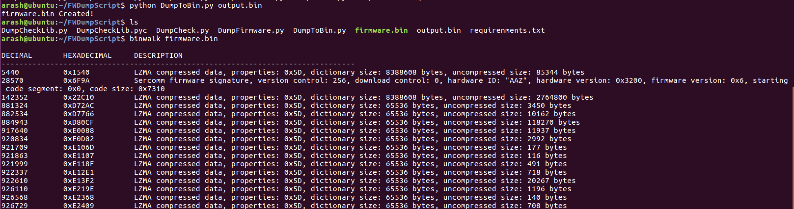
And here we can see our valid Sercomm firmware signature again, identifying we successfully dumped valid firmware.
Conclusion
As we can see, UART can be an extremely viable alternative to accessing and dumping a flash chip directly. We can access the underlying firmware, WHILE the machine is running, and use this to observe all operations and identify any weaknesses in the firmware through not only static analysis of the firmware bin but dynamic analysis of the IOT device as it's running as well.
In this example, UART gave us a somewhat limited shell that we were able to leverage to dump the firmware in an alternative matter, giving us the unencrypted firmware of the device at runtime for analysis (which could also provide interesting data like unpacked filesystems we may not have access to otherwise). In most devices though, UART can give you full root shells to the device, allowing you to traverse it like any other Linux device, even allowing you to easily install back-doors within the OS without having to embed it within the firmware bin directly, which makes it quite useful for an attacker to know how to access.